 Contact
Testing Services
- HOME
- Advanced EMC Solutions - The SmartScan Series
- Testing Services
Testing Services
We provide contract testing services for both immunity and emission evaluations using API SmartScan.
The available test categories are as follows:

Emission (EMI) Testing
- SmartScan-EMI (EMI scanning)
- Electromagnetic field computation
- Phase measurement
- Near-field to far-field conversion

Immunity (EMS) Testing
- ESD scanning
- Current diffusion path visualization
- RF immunity scanning
Deliverables
- Test report
- SmartScan Viewer license (valid for two weeks) for scan data review
- Project files (data compatible with SmartScan)
Service Workflow
- STEP
- Initial consultation to understand customer requirements
- STEP
- Selection of appropriate techniques and test scheduling
- STEP
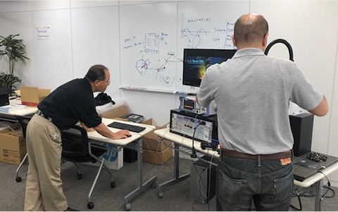
- Test execution (on-site observation available at our Osaka headquarters lab or test facilities)
- STEP
- Analysis of test results and preparation of the report
- STEP
- Delivery of the final report
- OPTION
- Consulting services for further improvement
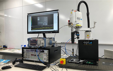
Equipment Used
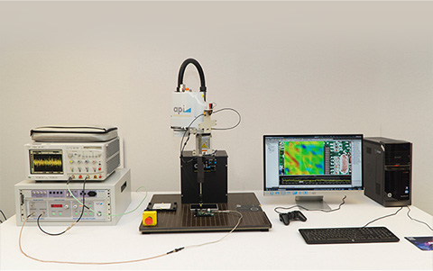
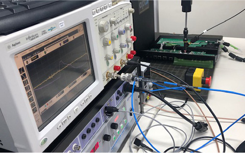
Measurement Environment
Test Case Examples
Case 1: ESD Issue on a Photo Frame PCB
SmartScan ESD
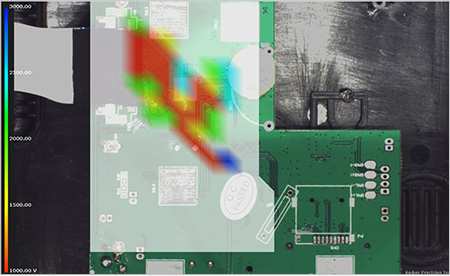
The PCB was operated under normal conditions while ESD pulses were applied.
Vulnerabilities were identified around the power supply section of the photo frame PCB.
Red-marked areas: System failure at 1 kV.
Blue-marked areas: System failure at 3 kV.
(TLP output: 1 kV minimum / 3 kV maximum, near-field probe Hz8 mm, scan pitch: 3 mm)
Case 2: ESD Issue on an IC Control PCB
SmartScan CS (Current Diffusion Trace)
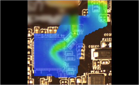
The PCB was kept in a non-operational state. A 200 V pulse from the TLP output was injected via the power supply, while the magnetic field was scanned using a near-field probe.
ESD was observed traveling along connector wiring and penetrating into the IC (highlighted by red circles).
(TLP output: 1 kV minimum / 3 kV maximum, near-field probe Hz8 mm, scan pitch: 3 mm)
Frequently Asked Questions
- ?
What preparations are required when requesting an ESD scan?
- A
You will need to provide an error-handling output (such as stop or restart) or a dedicated error detection module.
During ESD scans, an FD (Failure Detector) is used in conjunction with the ESD pulses generated by the TLP. The FD is equipped with four digital and four analog input jacks.
Since error output methods vary depending on the DUT, some common examples are shown below:
[Examples of Error Detection Methods]
- Using a photo sensor to detect blinking of an error lamp (LED, 7-segment display, etc.).
When the light turns off, it is interpreted as an error. - Using sound input: when the device shuts down or reboots, an error signal is generated and detected.
- Using a microcontroller board or similar device to output the error as a signal.
Note: Error handling depends on the DUT. Please feel free to contact us for consultation.
Partner Companies for Contract Testing
Support for ESD Testing and Current Spread Path Tracing
CONTACT US
For more information, please contact us
+81-6-6377-2451
Business Hours: Weekdays 9:00-18:00 (JST)