 Contact
Immunity Features

- HOME
- Advanced EMC Solutions - The SmartScan Series
- Immunity Features - ESD Scan
ESD Scan
- Generates susceptibility maps (reproducing gun-test failures)
- Supports TLP up to 8 kV (tr < 300 ps)
- Automated error detection
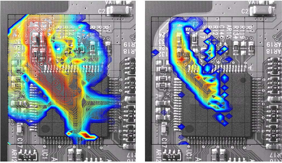
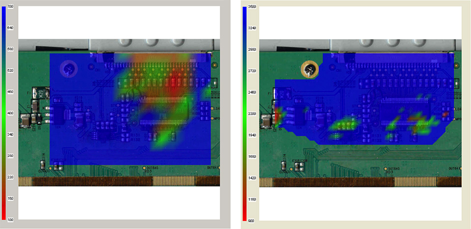
When an ESD simulator (ESD gun) discharges into the DUT’s test points, current flows through the chassis and into the internal PCB. This current radiates electromagnetic fields, coupling into PCB components and traces, and induces unwanted voltages and currents in the circuit. These induced signals can cause functional disruptions or even catastrophic failures. However, a gun test alone cannot pinpoint the exact location of the failure.
With ESD scanning, the DUT enclosure is removed and the exposed PCB is directly approached using magnetic or electric field probes. Current from the TLP (Transmission Line Pulse) source is applied through the probe. The probe couples into components and traces on the PCB, locally reproducing the DUT’s malfunctions.
What ESD Scanning Provides
- Emulates the electric and magnetic fields that induce voltages and currents in the circuit
- Identifies the susceptibility level at specific locations on the PCB
- Records the DUT’s response to the induced voltage or current
- It is also possible to use a dedicated probe to directly inject current into the circuit and monitor the DUT’s response
For a demonstration, see the video: “Introduction to the SmartScan ESD Scanner (English)”.
Use Cases
- Debugging malfunctions or failures caused by ESD (pinpointing error locations after gun tests)
- Performance comparison and quality inspection of components or modules with identical functions and specifications
- Certification of components and modules for system-level ESD immunity
Debugging ESD Failures
ESD scanning is a powerful tool for pinpointing and debugging failures in accordance with IEC 61000-4-2. It can also be used to evaluate ESD-protected modules.
Performance Comparison and Quality Inspection of Identical Components or Modules
ESD scanning is highly effective for comparing multiple suppliers’ components with the same function and specifications. It helps identify which supplier’s parts are least likely to experience ESD-induced failures.
Certification of Components and Modules for System-Level ESD
It is advisable to screen potentially problematic ICs or modules before assembling them into a completed system. By performing ESD scans, you can build a database of scan results for each product. This data provides valuable information for determining susceptibility levels to ESD immunity.
The ANSI/ESD SP14.5-2015 standard, approved in 2015, provides high-quality guidelines for near-field immunity testing using near-field probes to discharge static electricity on components, modules, and PCBs, helping to identify failure points. This testing method is highly effective for identifying the root causes of ESD-related problems.
Required Equipment
- SmartScan-ESD (software)
- TLP (Transmission Line Pulse)
- ESD probes
- Failure Detector
TLP (Transmission Line Pulse)
TLP generates rectangular pulses with a 500 ps rise time. For the rationale behind using TLP as the source of ESD disturbances, please refer to the paper (in English) on API’s website.
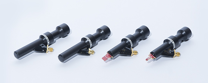
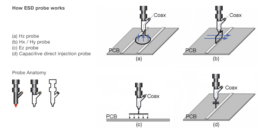
Probes
API-designed ESD probes are engineered to maximize the emission of electric and magnetic fields. Various sizes of magnetic and electric field probes are available. The figure below illustrates the concept of four different probe types.
Failure Detector
Scanning can be automated using a Failure Detector. This allows operators to leave the scanner unattended until scanning is complete, significantly improving the efficiency of ESD scans. The device can monitor four analog and four digital inputs, outputs from photo sensors, and a 1 kHz microphone signal. It also includes AC relays (120–240 V) and NO/NC DC relays for cycling the DUT power, all controlled via software.
Since the definition of an error (how the error output is generated) can vary greatly depending on the product, the Failure Detector can be customized for each DUT and test. For more details, please contact us.
Test Flow
- STEP
- Power on the DUT.
- STEP
- Move the probe to the test position.
- STEP
- Apply ESD (direct field injection).
- STEP
- Monitor the DUT’s response.
- STEP
-
If a failure is detected:
- Power cycle the DUT.
- Reduce the TLP voltage to the minimum level set by the user.
- Reapply the ESD.
- Gradually increase the voltage from the minimum level.
Plot the voltage on-screen at the point where the failure occurs.
- STEP
- Move to the next test point.
Immunity Features
CONTACT US
For more information, please contact us
+81-6-6377-2451
Business Hours: Weekdays 9:00-18:00 (JST)