 Contact
Emission Features
- HOME
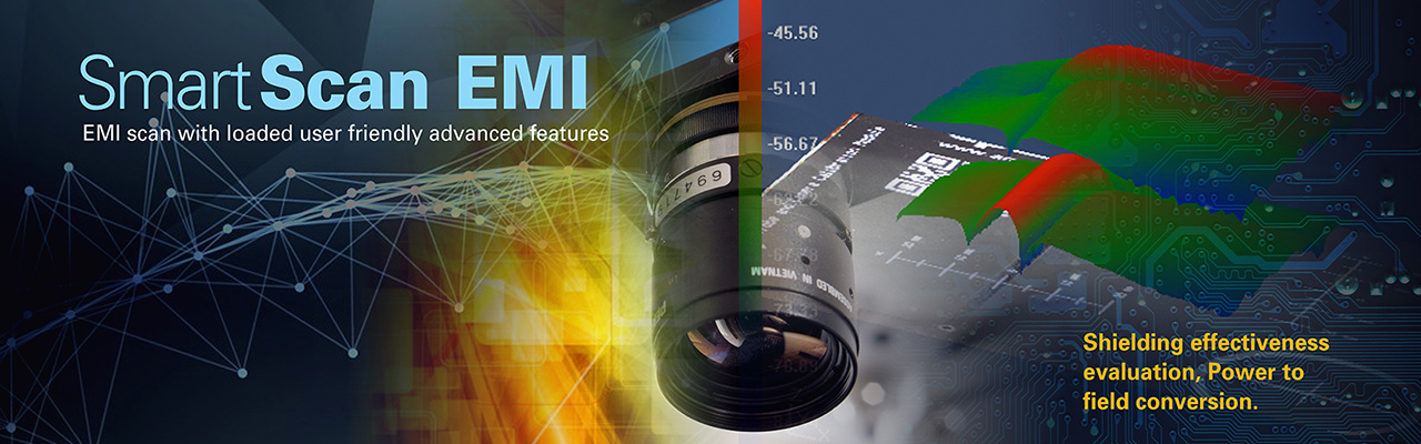
- Advanced EMC Solutions - The SmartScan Series
- Emission Features - Phase Measurement
Phase Measurement
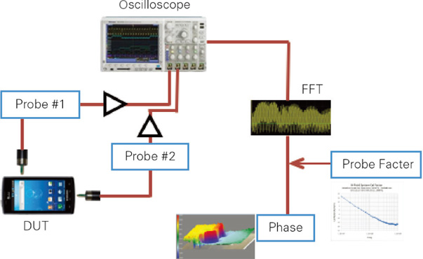
- Broadband automated phase measurement
- Uses two probes: a reference probe and a measurement probe
- FFT transformation using an oscilloscope or VNA
Near-field scanning has long been used to identify strong local magnetic sources and is commonly employed to pinpoint causes of unwanted emissions, antenna structures, and coupling paths.
The strength of a local magnetic or electric field does not always indicate which sources couple efficiently to a well-designed antenna or form a good antenna structure. Such issues often rely on the experience of EMC engineers. For example, a weak 125 MHz signal appearing in an unexpected location may be a precursor to a design flaw, even when a strong 125 MHz signal is present on the clock.
Similarly, a very localized and strong emission source may have less effect in the far field than a weak, distributed noise source such as a heatsink. To accurately identify the cause of EMC problems and to obtain models suitable for numerical simulation or module/IC verification, a powerful scanning technique is required.
According to Maxwell’s equations, by determining the magnitude and phase of the near magnetic field around a noise source, it is possible to reconstruct a model of the source to reproduce its radiation or simulate its far-field emissions. The key requirement in this process is information about the phase of the magnetic field, defined as the phase difference between a reference point and all other field points.
Phase can be measured in various ways, but the uniqueness of API’s phase measurement technology lies in its broadband and fully automated approach.
Use Cases
- Conversion from near-field data to far-field
- RFI analysis
Required Equipment
- SmartScan-PM software
- Oscilloscope or VNA (meeting the requirements for each frequency range)
- EMI probes
- Any hardware required for system calibration or signal generation (e.g., comb generator)
Please also see our Rohde & Schwarz products
Emission Features
Immunity Features
CONTACT US
For more information, please contact us
+81-6-6377-2451
Business Hours: Weekdays 9:00-18:00 (JST)